Showing posts with label Downhole Equipments. Show all posts

Multisensor


Operators can use a down hole sensor to obtain a direct measurement of ESP and well performance.
Direct, accurate measurements are of more value than a simulated or calculated value.
Real Time measurements provide the tool to perform in depth data validation & analysis.  

For real results in production optimization take  a look at overall  well performance – not just the lifting mechanism.

The Multisensor measures:
  • Intake Pressure
  • Discharge Pressure (optional)
  • Intake temperature
  • Motor temperature
  • ESP Vibration
  • Cable Insulation

The monitoring system has three main sections :

1. Multisensor Downhole Tool
2. Integrated Surface Panel

3. Multisensor Choke Console


The Multisensor is connected to the wye point of the motor and is  fitted  to the bottom of the ESP Motor.

The Integrated Surface Panel provides:
  • The power for the Multisensor
  • Signal decoding for the Multisensor
  • Data display and storage
  • ESP protection though Alarm and Trip functions

The choke provides high voltage isolation between the high voltage of the ESP system and the ISP The Choke can be supplied either with or without an enclosure

The MultiSensor downhole system measures up to 5 parameters, these being Pi, Pd, Ti, Tm and vibration. 

Downhole sensors are calibrated to international standards.

Data is transmitted via the motor power cable to the surface.

The downhole electronics are Qualified for their operation in this environment.

Measurement: Sensors : 

Intake Pressure : Measured using a 400 Bar sealed strain gauge pressure transducer.  

The voltage output from the transducer is near linear with pressure. 

Discharge Pressure : Measured in the same way as intake pressure but with a ¼ inch sealed control line extending to above the pump discharge.

Intake Temperature : This is measured by utilizing the semi-conductor temperature sensor which is both linear and accurate in temperature measurement. The voltage output varies with temperature. 
The temperature sensor is calibrated in an oven.

Motor Temperature : Either motor winding with a thermocouple fitted in the motor winding, or motor oil with the thermocouple fitted into the oil at base of the motor. Measured using J-type thermocouples and works by means of a temperature difference system. For absolute temperature the Intake temperature is used as the reference. The temperature sensor is calibrated in an oven.

 Vibration : Measured by means of a calibrated accelerometer fitted inside the MultiSensor. 

Current Leakage : The MultiSensor system measures leakage to earth through the ESP system and also when the MultiSensor is isolated from the rest of the system. This is referred to as active and passive current leakage


What Can We Do With This Data…..?

  • Monitoring
  • Trending
  • Protection
  • Validation & Analysis
  • Use the analysis results for optimisation 


Pressure Protection :


Intake Pressure :
  • Low trip:- Protect Against Pump Off
  • Low Fluid Level
  • Gas Breakout
Discharge Pressure :
  • High trip:- Protect Against Shut In
  • Closed Valves
  • Heavy Fluid Slugs
Delta Pressure :
  • Low / High trip:- Upthrust/Downthrust
  • High Flow conditions
  • Low Flow Conditions

Temperature Protection :

Intake Temperature :
  • High trip:- Protect Excessive Intake Temp
  • Recirculation

Motor Winding Temperature :
  • High trip:- Protect Excessive Motor temp
  • Low Flow
  • High Load
  • Anything that will cause the Motor to Heat

Vibration and Current Leakage :

Vibration :
  • High Alarm:-ESP mechanical damage
  • High solids  production
  • Warning of Mechanical wear
  • Resonance ‘frequency fine tuning’

Current Leakage :
  • High Alarm:-Electrical system deterioration
  • High Pump Heat (MLE)
  • Resistance Breakdown
  • Phase to ground warning


Using the Analysis to Optimize Production :
  • Model the whole hydraulic system
  • Use Phoenix data to validate important  parameters :
  1. Water cut & GOR
  2. Flowing Bottom Hole pressure
  3. Pump Operating point (down hole flow)
  4. Reservoir pressure
  5.  Accurate Productivity Index
  • Use the results to predict improved optimisation :
  1. Better runlife 
  2. More net oil 


Motor


ESP Motor consists of a stator housing, head and base and rotor-shaft subassembly. Three-phase power is fed through the cable pothead into the motor head, to the stator windings causing the rotor-shaft subassembly to rotate, delivering torque to the pump.

The stator takes electrical energy (KVA) from the surface and converts this to magnetic energy in the stator laminations.
The magnetic field of the stator induces current  (electrical energy) flow in the rotor.
This electrical energy in the rotor induces a secondary magnetic field in the rotor laminations.
The magnetic poles of the rotor will be attracted to (and repelled by) the magnetic poles in the stator.
As the stator magnetic field moves, the rotor will move to try to follow it.

The Downhole Electric Motor : 
  • 3 phase
  • Squirrel cage : Because the structure resembles the cage used to exercise squirrels, rotors of this type are called “Squirrel-Cage” rotors.
  • 2 pole
  • Induction Motor.


Motor Construction :

1-Stator :

Because of the way the stator is wound, the three phase power establishes a two pole magnetic field within the stator.


The stator is the core or electrical field of the motor.
The stator is composed of the housing material for a desired diameter, the stator core, and the stator windings .
The stator core is composed of laminations stacked under pressure to insure a permanently tight core.

Laminations are thin sheets of die-punched steel or bronze material. 


The stator is hand wound by experienced craftsmen.  Each stator is wound in three phases with the determined amperage and voltage for each order placement.
The windings are made from either Polyimid or PEEK material, for primary magnetizing winding wound through the die-punched slots in the stator core. 


2- Rotor :

The rotor is a device that rotates inside of the stator core.
The rotor is made up of rotor laminations that are smaller in diameter from the stator laminations and these creates the iron core.  Inside each slot are copper bars with supporting copper end rings.
The bars are shorted together at each end by a rotor “end ring”.  Depending on the motor, the end ring is either braided or brazed to the rotor bars.


3- Rotor Bearings :

The Bearing Material is Babbitt-lined steel and machined after processing.  There are fluid holes to insure oil circulation and wide angle oil grooves on the OD to distribute lubrication evenly over the entire length of the bearing surface.
The bearing sleeve is a bronze material for the sleeve construction of the bearing.  This part is keyed to the shaft and the hole on the sleeve is aligned with the hole on the shaft to insure proper cooling and lubrication.
Its main purpose is to provide the axial and radial thrust capabilities.


4- Thrust Bearing :

The motor thrust bearing is installed at the top of the rotor string.  It is designed to hold the weight of the entire rotor assembly.
The thrust bearing limits on the system will indicate the type of load required for the selected bearing material.


5- Pothead :

There is tape-in potheads and plug-in type for motor lead connection to the pothead.
Historically tie in potheads have been more reliable than plug in ones.
The disadvantage is the time taken for connections.


Tandem Motor Configuration :

Motors may be combined in tandem to provide the total power required by larger pumps
The motors should preferably be identical, with the same power ratings, and nameplate voltages and currents.

With two motors we double the HP (add the two HP’s together).  We also double the voltage but the amperage remains the same.
Always take care when adding motors together so that the total voltage does not exceed the system limits. For example do not try to put 3400 volts on a 3 kV cable.  

The top tandem motor is always a UT, the middle section(s) is a CT, and the bottom most is either an LT or a CT depending on whether a sensor will be installed or not. Depending on the type of motor, an adapter is required.

1- Single Section (S) - The motor head is designed to accept the power cable connection on top. The base has an integral "Y" connection at the bottom connecting the windings together and cannot be connected in tandem with any other motor.

2- Center Tandem (CT) - The motor head is designed to connect to the bottom of an upper tandem or center tandem motor and a base designed to connect to another center tandem motor, a lower tandem or a universal base. All flange connections are designed so that windings from one motor will connect to the corresponding windings
of the adjacent motors.

3- Upper Tandem (UT) - The motor head is designed to accept the power cable connection on top and either a center tandem motor, lower tandem motor, or universal base on the bottom.

4- Lower Tandem (LT) - The motor head is designed to connect to the bottom of an upper tandem or center tandem motor and an integral "Y" connection at the bottom connecting the windings together.


UMB is a Universal Motor Base. Use a UMB to provide a filter base on a UT or CT motor where no integral gauge is used.
UMH is a Universal Motor Head. Use a UMH to convert a CT or LT motor to connect to the protector and flat cable, but generally this should be a last-resort for emergencies.


Protector


The Protector has four primary functions:

1. Couples the torque developed in the motor to the pump via the protector shaft.
2. Prevents entry of well fluid into the motor.
3. Provides pressure equalization.
4. Houses the bearing to carry the thrust developed by the pump.


Keep Out Well Fluids :


One of the main functions of the Protector is to keep well fluids out of the motor where they could potentially do harm.
Some types of water well motors are actually open to the well fluid and no effort is made to keep it out.

In the oil well environment, the produced fluids are much more aggressive than typically found in water environments and, if allowed to contact the inside of the motor, may cause a premature failure.

Protector Chambers :

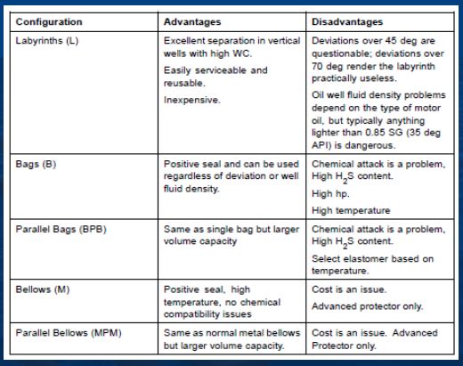
Labyrinths, Bags, Metal Bellows.
Chambers can be connected in series or parallel.
Every series can have different section combination.


Labyrinth Protectors :

 One such Protector type is the "Labyrinth" type.  
The labyrinth design uses the difference in specific gravity of the well fluid and the motor oil to keep them apart even though they are in direct contact. 


There will be cases where a labyrinth will simply not work.  In cases where the well fluid is  lighter gravity than the motor oil (i.e. about 0.85), the motor oil will go to the bottom of the chamber  rather than the top causing the motor fluid to be displaced by well fluid pretty quickly.

If the well fluid is about the same gravity as the motor fluid or lighter, this type of Protector should not be used.

Labyrinth Protectors also will not work in horizontal or highly deviated wells.  The gravity separation design requires the unit to be mostly upright. This Protector can operate in some amount of deviation but the expansion volume is somewhat reduced.

Many times the labyrinth protector is "checked" in the field to determine if water got into the bottom of the unit.  If this is done,always do it before the unit is laid down on its side. Once on its side, water initially in the bottom of the chamber may redistribute itself since the U-tube restriction is effectively removed.

Advantages :
  • Excellent separation in vertical wells with high WC.
  • Easily serviceable and re-usable
  • Inexpensive. 
Disadvantages :
  • Deviations over 45° are questionable;
  • Deviations over 70° render the labyrinth practically useless.
  • Oil well fluid density problems depend on the type of motor oil, but typically anything lighter than 0.85SG (35 °API) is dangerous


Positive Seal Protectors :

For applications where the well fluid and motor oil gravities are similar or where a well is highly deviated, a different Protector design uses a "positive seal" or "bag" to physically separate the two fluids.

This is similar to the "bellows" found in some water well motors except that the bag has a much greater capacity for expansion and contraction than a typical bellows.

The bag is made of a high temperature / high performance elastomer which can withstand the harsh Downhole environments typically encountered.  The bag keeps the well fluid on the outside and the clean motor oil on the inside.

When the motor oil expands or contracts, the bag simply flexes to accommodate the necessary volume change.


Advantages :
  • High Temp / High Performance Elastomer;
  • Accommodate volume changes

Disadvantages :
  • Limited operating temperature as rubber 
  • Aflas bags are rated to only 400 degF
  • Rubber bags are exposed to chemical attacks
  • Gas migration through rubber bags
  • Hardening and loss of elastomer flexibility

Thrust Handling :

Another function of the Protector is to absorb the thrust generated by the pump whether it is upthrust or downthrust.  The Protector thrust bearing gives a very large surface over which to absorb thrust.  In addition, it does so in a nice clean oil environment which greatly prolongs the ESP unit life.

Care should always be taken to select a Protector series which has a thrust bearing rating greater than the maximum thrust the pump will generate.


When sizing a Protector for an application, it is sometimes necessary to consider the power used by the Protector when sizing the motor.  

In larger diameter / higher thrust load applications, failure to do so could result in an overloaded motor.

For smaller diameter and/or lower load conditions, the additional power consumption is usually insignificant.

Motor Torque :

One other function which the Protector carries out is transmission of the motor torque to the pump since it is physically located between the two. Although this may seem a little trivial, in the selection process we need to be certain that the Protector shaft is capable of delivering the full torque required without exceeding its yield strength which could result in a broken shaft.


Pressure Equalization :

The ESP motor, unlike a surface motor, undergoes very wide swings in pressure.  

When the unit is first installed in the well it goes from atmospheric pressure up to the very     high bottom hole pressure of the well.

When the unit is operated, internal heating causes the motor oil to expand which would add even more pressure if it did not have some place to go.  If the unit is stopped and allowed to cool down, the oil will contract which would create a vacuum in a sealed system.

The Protector simply keeps the pressure on the inside of the unit the same as the pressure on the outside of the unit regardless of what the external pressure is.

Since the bottom of the Protector is open to the motor, the motor pressure remains the same as that in the well annulus around it.

By maintaining a negligible pressure difference, there is no tendency for the well fluid to penetrate into the motor.


Connection Types :

A protector will always have multiple chambers connected together.
  • Connected in series (designated with an “S”), redundant seal
  • Connected in parallel (designated with a “P”), larger capacity
Series Configuration :

A series connection is simply one in-line after the other just like series resistors in an electrical circuit.  

For well fluid to enter the lower chamber, it must completely displace all the oil in the upper chamber first.

So having two bags in series means the lower bag is a redundant seal to the upper bag and is there as "insurance" in case the upper bag fails for some reason.

There is no additional expansion capacity in "series" systems.

Parallel Configuration :

Two bags in parallel, on the other hand, do double the available expansion volume.  This is useful in higher horsepower applications (larger motors hold more oil) where the natural expansion and contraction might exceed the capacity of one bag.

If only one bag is used and the capacity is exceeded, the unit will allow well fluid penetration so two bags eliminates this possibility.


Protector Design :


The previous illustration showed some of the possible combinations.  Regardless of what configuration is chosen, the Protector function is essentially the same.

The naming convention for modular Protectors is simple and easily shows how a protector is designed.

In naming, always start from the top and move downward.


Advanced Gas Handler AGH


The primary aim of the Advanced Gas Handling system is to avoid "gas-locking" in the pump which can result in inefficient cyclical operations and possible premature mechanical failure if not properly controlled.
The AGH does not separate gas - but conditions it by compressing the total fluid; so it can be produced by the pump.

The AGH is designed to improve the overall lift efficiency of a submersible lift installation by maintaining a higher gas to liquid ratio in the tubing string. 
The higher GLR will in act to reduce the hydraulic horsepower required to lift an oil well producing oil, water and gas.  

The AGH can be used with a standard intake or with a gas separator.The choice will depend on how much free gas will be present at the intake for producing condition and on whether there is a packer preventing gas production up the annulus.

Advanced Gas Handling Objectives :

  • Increase a pump's ability to produce gas without "gas locking".  
  • Utilize gas to improve overall lift efficiency.
  • Allows usage of ESPs below packers in gassy wells 


Principle of operation for the AGH :
Increase gas handling ability with minimal head loss Methods:

  • Homogenize the mixture
  • Reduce bubble size 
  • Put gas back into solution 
  • Help gas to move to main stream
Turbulent flow in the pump breaks the gas up into fine bubbles at the impeller entrance.
During flow through the impeller the gas bubbles tend to lag  behind the liquid in the lower pressure area of the impeller.
Centrifugal force  flings the higher density liquid towards the circumference – the lower density gas accumulates below it in the impeller eye. As the gas increases the liquid production decreases.

Mixing (or crushing) the gas bubbles is necessary to aid flow.
The key issue is to reduce the impact of the centrifugal force which promotes the gas separation.
Balance holes exist in all impellers. In AGH’s an additional passage allows re-circulation of the fluid.
This allows separated gases to be re-mixed with the liquid which increases the pumps gas volume recovery ability. 

The AGH results in stable operation with reduced restarts due to underload shutdown (i.e. gas lock).  This improves production and enhances reliability...


Benefits of AGH :

1- Expand applications that can be produced with an ESP :                                                                                                    
  • Replace gas-lift
  • De-water gas wells
  • Produce gassy well below a packer

2- Increase production in wells experiencing downtime due to gas-locking :
  • Continuous stable operation
  • Benefit of gas lift effect in the tubing

3- Increase production in wells that have been limited to high intake pressures to keep stable operation :
  • Continuous stable operation at lower intake pressures - higher production rate possible


Gas Seperators

Impact of Gas on an ESP :

When free gas is present in the first stage impeller (or first few stages), it takes up useable space and restricts the volumetric efficiency of the pump.  The result is a decline in expected production.  In fact, if the impeller eye fills completely with gas, the pump will "lock" or stop producing at all.

Gas Related Problems in an ESP :
  • Vapor can tend to "Gas Lock" a pump leading to surging and 
  • premature pump failure.  
  • Vapor does not lubricate bearings well.
  • Pumping efficiency is reduced.  
  • Limits production


Gas locking can cause either current fluctuation or pump shut down on underload .
A device which handles more free gas will results in increased daily production .

There are two basic types of intake Sections:
1- Intakes
2- Gas Separators
     • Static 
     • Dynamic

Pump Intakes : 
A standard intake does not separate gas.  Some gas separation might occur with a standard intake, but it will only be Integral Intake Bolt-on Intake, but it will only be natural separation due to some of the gas not turning and going into the intake when the rest of the fluid does.


Gas Separators : 
A gas separator is still an intake, but with some special features designed to keep free gas from entering the pump.

Static Gas Separators :

Original gas separator designs were based on increasing gas separation by forcing the fluid flow to reverse in the wellbore.  This is where the name of this type of gas separator, REVERSE FLOW, comes from. Since this type of gas separator does no real "work" on the fluid, it is also called a "static" gas separator.


As well fluid enters the gas separator it is forced to change direction.  Some of the gas bubbles continue to rise instead of turn or rise inside of the gas separator, exit the housing and continue to rise.


Dynamic Gas Separators :

Dynamic gas separators actually impart energy to the fluid in order to get the vapor to separate from the liquid.  The original gas separator was called a KGS (short for either Kinetic Gas Separator or Kobylinski Gas Separator).  This design uses an inducer to increase the pressure of the fluid and a centrifuge to separate the vapor and liquid.  This design could likewise be called a centrifugal gas separator. 


The rotary gas separator design works in a similar fashion to a centrifuge.  The centrifuge "paddles" spinning at 3500 rpm cause the heavier fluids to be forced to the outside, through the crossover and up into outside, through the crossover and up into the pump, while the lighter fluid (gas) stays 
toward the center, and exits through the crossover and discharge ports back into the well.


Gas Separators Efficiency :

Normally we would use rule-of-thumb estimates like the following based on experience:


Testing conducted at Tulsa University actually showed that natural separation could be from 20% to  60 % and that with a rotary gas separator, total separation efficiencies could be as high as 99 %. The testing also indicated that gas separators (all types) do have definite flow ranges where they are effective and other flow ranges where they are not. 


Intake


Intakes As the name suggests “Intakes” are where the well fluid  enters the Submersible Pumping System .
There are three types of intake Sections:
1- Standard Intakes or BOI (bolt on intake) are designed to have low loss rates at high flow rates
2- Integral Manufactured as part of the pump at bottom of single/LT pump
3- Gas Separators


Standard, BOI and integral intakes do not separate gas.  
Some gas separation might occur, but it will only be natural separation due to a percentage of the gas not turning and going into the intake when the rest of the fluid does.

Intakes can be either ARZ, which is the preferred configuration, or standard.
The ARZ intake uses Zirconia bearings and sleeves to better protect against abrasive wear and lateral vibration.  This is important so near a protector seal.
ARZ Intakes are available in 338, 387, 400, 540, 562, and 675 series.
Intakes are available in various combinations of Carbon Steel and Redalloy, Monel and Inconel shafts, ARZ, ARZ-SS and ARZ-ZS bearing pairs for all pump series.

Rules for intakes :
  • Match series of pump
  • Match series of protector
  • Bearing same as, or better than pump
  • Shaft strength same as, or better than pump
  • Housing material should match pump


Pump


Centrifugal pump is a multistage pump, containing a selected number (application dependent) of impellers equipped with vanes, inside a closely fitted diffuser,  located in series on an axial shaft, driven by the electric motor.

Centrifugal Pump is a machine that moves fluid by spinning it with a rotating impeller into a diffuser that has a central inlet and a tangential outlet.
The path of the fluid is an increasing spiral from the inlet at the center to the outlet tangent to the diffuser.
The impeller’s job is to transfer energy by rotation to the liquid passing through it, thus raising the kinetic energy.
The diffuser section then converts this energy to potential energy, raising the discharge pressure. From there, the rotation of the high-speed impeller throws the liquid into the diffuser.

There are two types of impellers that determine the amount of flow available for the specific design.
The difference between these two types of designs is described by the pump impeller vane angles and the size and shape of the internal flow passages : Axial (Mixed) Flow and Radial (Pancake) Flow.

A mixed flow impeller has vane angles at close to  45 degrees, and therefore, are usually found in pump ranges for higher flow rates.


A radial flow (pancake) impeller has vane angles at close to 90 degrees, and therefore, are usually found in pump ranges for lower flow rates.


Pump Construction :
There are two types of pump stage construction for ESP oil field applications:
1- Comprssion
2- Floater


In a compression pump, all the impellers are rigidly fixed to the shaft so that if an impeller wants to move up or down, it will take the shaft with it.The impeller is normally sitting down on its lower diffuser during assembly due to gravity.  Because of this, the pump shaft is "raised" with shims in the coupling so that the impeller is not allowed to touch the diffuser after final assembly.  This allows all thrust developed in the pump shaft to be transferred to the protector shaft directly.
Why use Compression Pumps?
  • Some stages generate too much thrust to be handled by a thrust washer in the stage.
  • Some fluids (e.g. liquid propane) do not have enough lubricity to properly lubricate a thrust washer.
  • If abrasives or corrosives are present, it may be beneficial to handle the thrust in an area lubricated by motor oil rather than well fluid.
  • Occasionally in very gassy wells, the flow volume changes so drastically within the pump that parts of a floater pump could be in very severe thrust while others are not so a compression pump could be one alternative.
  • Since all the thrust is handled in the protector, as long as the protector has a great enough capacity, the pump operating range can be extended over a much wider area without any increased wear or reduced life.

Since a floating impeller is free to move up and down the shaft, the only thing to stop it is either the upper or lower diffuser.  "Thrust washers" are provided at all mating surfaces between the impeller and diffuser to absorb any thrust generated. 
We lose efficiency in the upthrust position because of the fluid's ability to recirculate from the high pressure to low pressure eye area.  In addition to loss in efficiency, this can promote erosion in the diffuser in abrasive fluids.
Why use floater pumps?
  • Since each stage handles its own thrust, a very large number of stages can be put in a pump without having to worry about protector bearing capacity.
  • Floaters are also very good with mild abrasives since they prevent material from getting into the radial bearing area.
  • Floaters are much more forgiving in manufacturing since tolerance stack-up is not a concern.
  • Easier field assembly - no shimming required.
Pumps come in several different configurations. Most pumps (especially the smaller diameter ones) come as "center tandems" (or -CT type).  
Other types are "upper tandems" (-UT), "lower tandems" (-LT) and "single" (-S) pumps.
The actual pump stages are no different regardless of what "type" it is. The difference in the pumps depends on what they look like at the ends.


Pump Nomenclature: 
Frequently Used Abbreviations :