
The Transformer is an electrical device by which alternating current of one voltage is changed to another voltage.
How does it work?
A primary inductive coil around a common iron core creates a magnetic flux linkage inducing a current into one (secondary) coil or more (tertiary/phase shifting) coils.

- Dry Type (Air Cooled)
- Oil Filled
- Power (Between Generation and Transmission Lines)
- Distribution (Transmission Lines and service 5-500kVA)
- K Rated (Harmonic Rated), VSD Rated
Transformer operation Principal :
Electrical energy can be transferred by mutual induction from one winding to another.
Mutual induction is the coupling of inductances by their mutual magnetic fields.
Transformers are electromagnetic devices that transfer electrical energy from one circuit to another by mutual induction.

When the primary winding is energized from an alternating current source, an alternating magnetic flux is established in the transformer core.
Transformers are used to step a voltage up to a higher level, or down to a lower level.
If the primary coil has fewer turns than the secondary coil, it is a step-up transformer.
If the primary coil has more turns than the secondary coil, it is a step-down transformer.


Transformers can be either single phase or three phase. A single phase transformer generally appears similar to the figure shown.

120 or 240 VAC single-phase transformers are used to supply lighting, receptacle, and small appliance loads.
A 240 VAC secondary can be tapped in the center to provide two sources of 120 VAC power.

Normally when using single phase transformers for three phase power, three individual transformers are connected together.
It is possible to connect them in various configurations.


Three-phase transformers are used when three-phase power is required for larger loads such as industrial motors.
There are two basic three-phase transformer connections, delta and wye.

Transformer Delta Connection :
The power supply leads are connected to one end of the coil of each of the transformers . The other end of each of the coils is connected to the next phase.

If the transformers are connected in "Delta", the voltage applied across the winding will be the same as the phase to phase voltage.
V-line = V-phase
I-line = I-phse x 1.73
This arrangement shows three transformers connected "Delta-Delta".

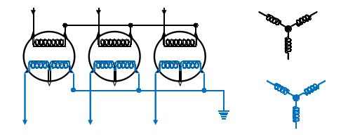
Transformer Wye Connection :
Each of the three power supply phases connect to one end of the coils of the transformers. The other ends of each coil are connected together, or to the system neutral.
V-line = V-phase x 1.73
I-line = I-phase
In this example, the transformers are connected "Wye-Wye". Please note that this connection is rarely used because of problems with the exciting current and induced voltage.

Transformer Wye/Delta Connection :
Typically used to step down voltage. An unbalanced load in this configuration does not cause the neutral to float.

V-line = V-phase
I-line = I-phse x 1.73
This arrangement shows three transformers connected "Delta-Delta".

Transformer Wye Connection :
Each of the three power supply phases connect to one end of the coils of the transformers. The other ends of each coil are connected together, or to the system neutral.
V-line = V-phase x 1.73
I-line = I-phase
In this example, the transformers are connected "Wye-Wye". Please note that this connection is rarely used because of problems with the exciting current and induced voltage.
Transformer Wye/Delta Connection :
Typically used to step down voltage. An unbalanced load in this configuration does not cause the neutral to float.

Transformer Delta/Wye Connection :
Typically used to step up voltage. The neutral will not float when the load is unbalanced.
The neutral point of the wye connection should not be grounded.

Transformer Rating :
- Transformers are rated in kVA (kilovolt-amps).
- This rating is used rather than watts because loads are not purely resistive. Only resistive loads are measured in watts.
- The kVA rating determines the current a transformer can deliver to its load without overheating.
- Given volts and amps, kVA can be calculated. Given kVA and volts, amps can be calculated.

The transformer voltage rating must not be exceeded, however, it is acceptable to apply less than rated voltage to the winding. When this is done, the kVA rating of the transformer must be derated by the same percentage that the applied voltage is to the nameplate voltage.
Typical Transformer Nameplate :

The following is an example of a Transformer adjusted to obtain a secondary volt of 2450 V when the primary volt is 480 V :

The following is an example of a Transformer adjusted if the voltage required in the secondary is 2450V but the primary voltage is only 330V :

Transformer 50 Hz operation :
The Fifty Hz transformers can be used on 60 Hz systems without derating or taking any other extraordinary precautions. It is possible in some instances to use 60Hz transformers on 50 Hz systems but some adjustment and precautions must be observed.
- The 50 Hz kVA rating will be reduced by the ratio of the 50 Hz voltage to the 60 Hz voltage.
- The 50 Hz primary voltage must be reduced by at least 12.5% from the 60 Hz rating.
Things to remember :
Often the field engineer will select a slightly higher voltage than that calculated.
This is because, in many power systems, the secondary voltage will be slightly lower when loaded than when the motor is not connected.
- Secondary winding can be split, then reconnected either series or parallel to obtain different winding voltages
- Primary is always connected to the power supply and sometimes referred to as line side.
- Secondary is always connected to the load and sometimes referred to as load side.
- H1, H2 ,H3- High Voltage winding has many turns
- X1, X2, X3 - Low Voltage winding has fewer turns
- Voltage Losses : When a transformer is fully loaded according to the amount of current that is being consumed the difference between no-load voltage and loaded voltage can be quite significant. (Due to impedance losses)
- Correct Voltage : Ensure the primary voltage does not exceed the winding voltage rating. Make sure output voltage is correct for the required surface voltage.
- Mount : Exposed or Covered bushings (Pole mounted or Pad mounted)
No comments:
Post a Comment